Blending and Transparency
This tutorial is all about rendering of transparent objects and how to handel them with node states.
TransparencyRenderer
The TransparencyRenderer is a NodeRendererState which handles transparency of nodes. To see how the TransparencyRenderer works, let’s take a look at a simple example.
Simple Example
In this example we will create three quads with different color, an alpha value of 0.5 to be transparent and put them in front of each other. To create these quads we take the buildMesh() method from the ShaderState tutorial and provide a parameter for each color channel, to create quads with different colors.
var buildMesh = fn(r, g, b) {
We create a red, green and blue quad and displace them along the z-axis.
var geo = new MinSG.GeometryNode(buildMesh(1,0,0));
var geo2 = new MinSG.GeometryNode(buildMesh(0,1,0));
var geo3 = new MinSG.GeometryNode(buildMesh(0,0,1));
// Displace the planes along the z-axis
geo2.moveLocal(new Geometry.Vec3(0, 0, -3));
geo3.moveLocal(new Geometry.Vec3(0, 0, -6));
Now we need to be careful where to put the TransparencyRenderer. It is a NodeRendererState and handels the rendering of all the nodes in the subtree. Therefore it needs to be places at our list node which then contains the quad’s geometry node as children.
var sceneNode = new MinSG.ListNode();
sceneNode += new MinSG.TransparencyRenderer();
sceneNode += geo;
sceneNode += geo2;
sceneNode += geo3;
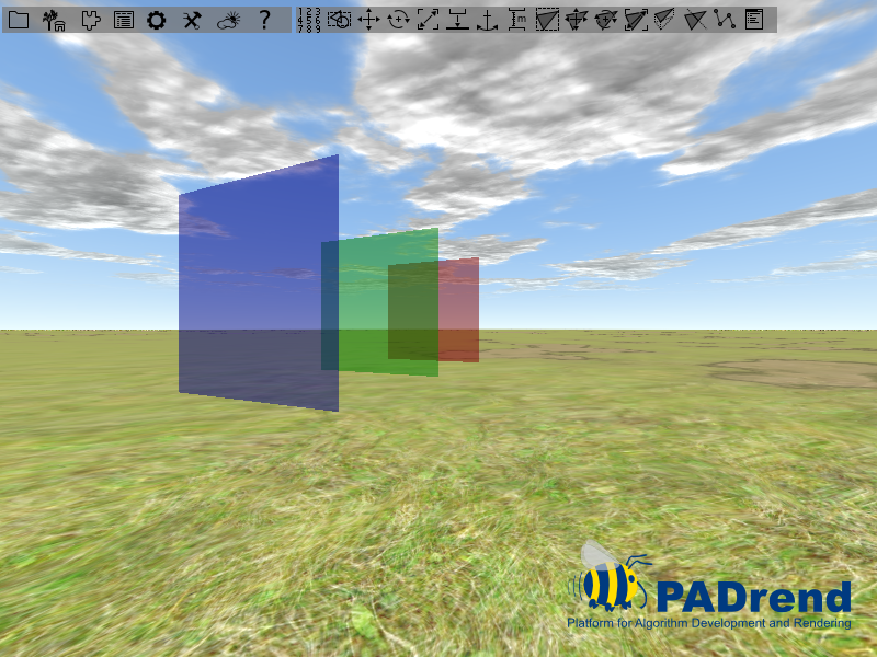
When we don’t insert the TransparencyRenderer then the result will look like this:
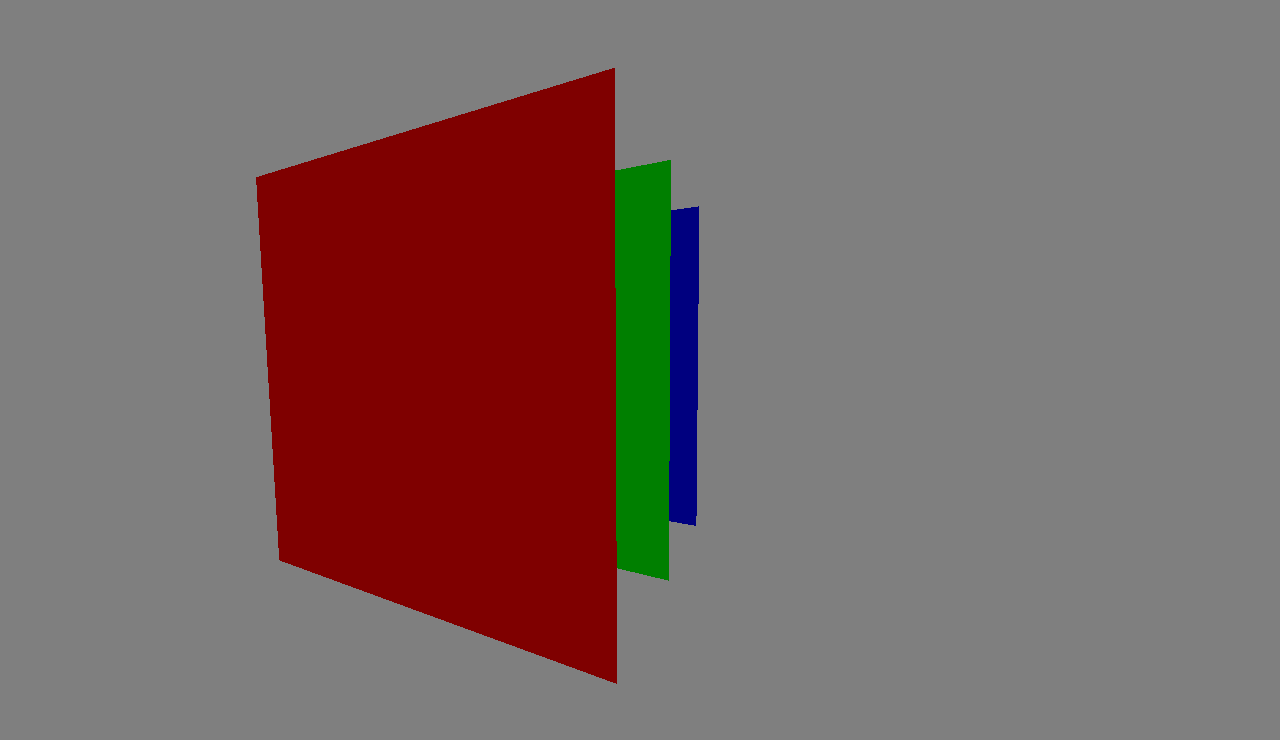
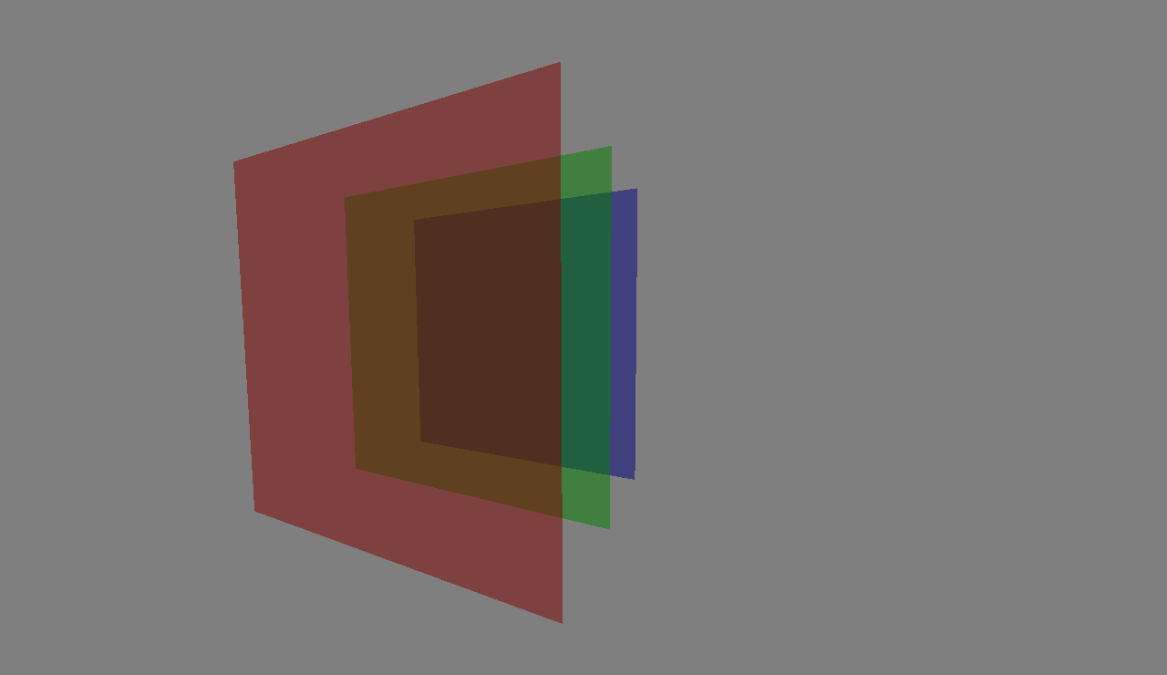
The quads are simply overlapping each other without transparency, although everyone of them has an alpha value of 0.5. When we insert the TransparencyRenderer at the list node we will see the transparency effect:
Blending State
As you may know when rendering colors are set in the frame buffer. Whenever there is an object that is closer to the camera than the current color in the frame buffer, the color gets replaced by the objects color. If using blending the color of the frame buffer and the objects color are combined. This is important in rendering transparent objects.
Blending Equation and Functions
This section is a summary of a book chapter.
You can find the complete chapter here.
The mixing of the colors is done by the blending equation.
In the following the color that can be found in the frame buffer is called destination color and the color the new object is called source color.
PADrend offers three different blending equations which can be set by the constants FUNC_ADD, FUNC_SUBTRACT and FUNC_REVERSE_SUBTRACT.
In the following FUNC_ADD is used to explain the blending equation.
The other equations are similar and will be introduced later.
FUNC_ADD is defined as follows:
Cf = (Cs * S) + (Cd * D)
Where:
- Cf: is the resulting color
- Cs: is the source color
- Cd: is the destination color
- S: is the source blending factor
- D: is the destination blending factor
You can influence the resulting color by setting the blending factors. In PADrend these are called Src Func and Dst Func. You can set the factors for blending the color and blending the alpha values indepndently. The blending functions are represented by an enum. In the following you can see which blending factors the enum values represent.
| Function | RGB Blend Factor | Alpha Blend Factor |
|---|---|---|
| ZERO | (0, 0, 0) | 0 |
| ONE | (1, 1, 1) | 1 |
| SRC_COLOR | (Rs, Gs, Bs) | As |
| ONE_MINUS_SRC_COLOR | (1, 1, 1) - (Rs, Gs, Bs) | 1 - As |
| SRC_ALPHA | (As, As, As) | As |
| ONE_MINUS_SRC_ALPHA | (1, 1, 1) - (As, As, As) | 1 - As |
| DST_ALPHA | (Ad, Ad, Ad) | Ad |
| ONE_MINUS_DST_ALPHA | (1, 1, 1) - (Ad, Ad, Ad) | 1 - Ad |
| DST_COLOR | (Rd, Gd, Bd) | Ad |
| ONE_MINUS_DST_COLOR | (1, 1, 1) - (Rd, Gd, Bd) | 1 - Ad |
| SRC_ALPHA_SATURATE | (f, f, f) | 1 |
| CONSTANT_COLOR | (Rc, Gc, Bc) | Ac |
| ONE_MINUS_CONSTANT_COLOR | (1, 1, 1) - (Rc, Gc, Bc) | 1 - Ac |
| CONSTANT_ALPHA | (Ac, Ac, Ac) | Ac |
| ONE_MINUS_CONSTANT_ALPHA | (1, 1, 1) - (Ac, Ac, AC) | 1 - Ac |
Depending on the combination of blending factors the outcome of the blending will differ.
As mentioned before beside different blending factors, there are also different blending equations.
You can find the definition of FUNC_ADD above.
The missing two are defined as follows:
FUNC_SUBTRACT:
Cf = (Cd * D) - (Cs * S)
FUNC_REVERSE_SUBTRACT:
Cf = (Cs * S) - (Cd * D)
As with the blending factors, changing the blending equation changes the appearance of your scene.
Example program
In this example we will build a scene made from four quads. Each quad has a unique color and gains a alpha value of 0.5, so that there is some transparency. There are two settings of blending functions in the code. You can switch between them by changing the value of the boolean variable useConstantAlpha.
//This variable is used to switch between two blending functions.
var useConstantAlpha = false;
The code for creating the quads is provided by a function so that it can be reused.
//Creates a quad with a specific color. The function returns a
//geometry node including the mesh of the quad. The z-parameter
//sets the quad's displacement along the z-axis.
var createQuad = fn(z, r, g, b){
    var meshBuilder = new Rendering.MeshBuilder();
    meshBuilder.color(new Util.Color4f(r, g, b, 0.5));

    meshBuilder.position(new Geometry.Vec3(-0.5, 0, z));
    meshBuilder.addVertex();

    meshBuilder.position(new Geometry.Vec3(0.5, 0, z));
    meshBuilder.addVertex();

    meshBuilder.position(new Geometry.Vec3(0.5, 1, z));
    meshBuilder.addVertex();

    meshBuilder.position(new Geometry.Vec3(-0.5, 1, z));
    meshBuilder.addVertex();

    meshBuilder.addQuad(0, 1, 2, 3);
    return new MinSG.GeometryNode(meshBuilder.buildMesh());
};
First we need to create the three quads. We use the z-parameter to position the quads along the z-axis. Next up we create a ListNode that combines the three nodes to a scene graph.
//Three quads
var node1 = createQuad(0, 1, 0, 0);
var node2 = createQuad(1, 0, 1, 0);
var node3 = createQuad(2, 0, 0, 1);

//Building the scene graph
var scene = new MinSG.ListNode();
scene += node1;
scene += node2;
scene += node3;
Next up we create the blending state. In an if statement two different blending functions are applied. To set a blending function the methods setBlendFuncSrc and setBlendFuncDst are used. Depending on the used blending function you may also need to call setBlendConstAlpha. Use setBlendEquation to change the blending equation. You can find the constants of the blending equations in the namespace Rendering.BlendEquation.
//Two setting two different blending functions. The boolean variable
//useCostantAlpha can be used to switch between both settings.
if(useConstantAlpha){
    blendingState.setBlendConstAlpha(0.3);
    blendingState.setBlendFuncSrc(Rendering.BlendFunc.CONSTANT_ALPHA);
    blendingState.setBlendFuncDst(Rendering.BlendFunc.CONSTANT_ALPHA);
}
else{
    blendingState.setBlendFuncSrc(Rendering.BlendFunc.SRC_ALPHA);
    blendingState.setBlendFuncDst(Rendering.BlendFunc.ONE_MINUS_SRC_ALPHA);
}
Below you find two images that show the difference between the blending functions set in the code. The first image shows the constant alpha blending function, the second shows the combination of SRC_ALPHA and ONE_MINUS_SRC_ALPHA.
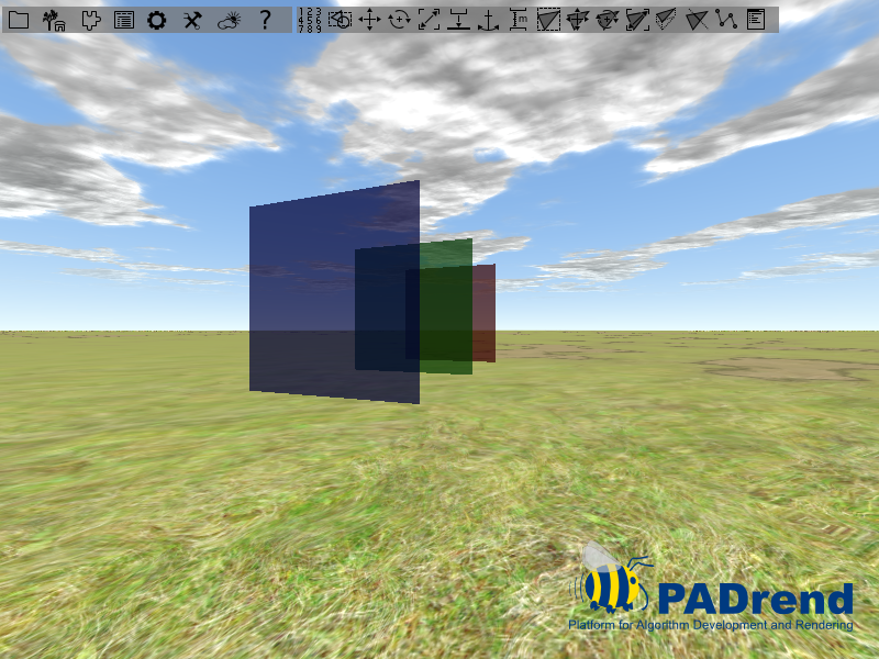
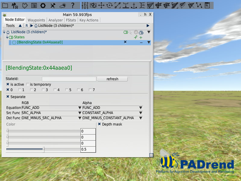
Feel free to experiment with different functions and equations. You can also use PADrend’s main window to manipulate the values. You need to navigate to the scenes root node to access the state.
AlphaTestState
The AlphaTestState deals with alpha values and decides whether to display it or not. To understand this state it’s best to take a look at a simple example.
Simple Example
For this example we will take the example from the TransparencyRenderer and create three different quads displaced from each other with different alpha values.
var geo = new MinSG.GeometryNode(buildMesh(1,0,0,0.5));
var geo2 = new MinSG.GeometryNode(buildMesh(0,1,0,0.3));
var geo3 = new MinSG.GeometryNode(buildMesh(0,0,1,0.2));
To make it more interesting we set the color of the upper left corner of our quads to be (1, 1, 1, 0), i.e. a white color without transparency.
    // Vertex 3:
    mb.position(new Vec3(0,10,0));
    mb.texCoord0(new Vec2(0,0));
    mb.addVertex();
The result will look like this:
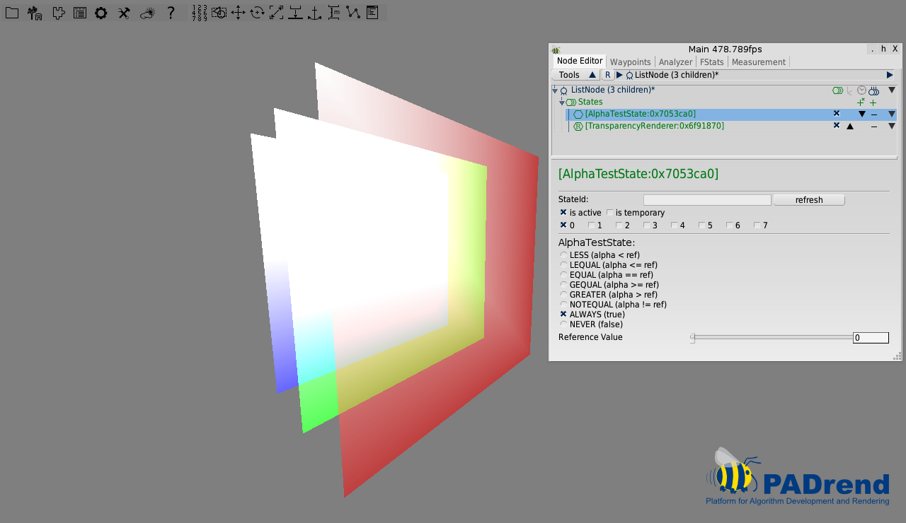
Due to interpolation of the color value across the quad performed by the GPU, the alpha value decreases from the upper left corner to the bottem right corner of the quads.
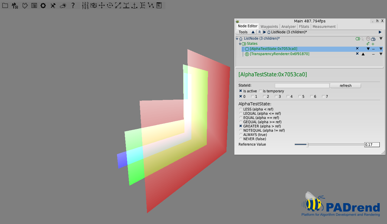
The AlphaTestState is added before the TransparencyRenderer to take effect:
sceneNode += new MinSG.AlphaTestState();
sceneNode += new MinSG.TransparencyRenderer();
Now you can go ahead and play around with the Reference Value and the options in the AlphaTestState. In our example we take the GREATER option and set the Reference Value to 0.17 telling the AlphaTestState to only draw pixels with an alpha value higher than 0.17. We can see how the upper left corner of all three quads isn’t drawn because the interpolated alpha values are below our Reference Value. You can try out other options and see how the state changes the rendering